The interface on network cards and Hubs is an 8‑core female socket (RJ45):

RJ45 interface on PC side, the network cable adopts 8‑core crystal plug:
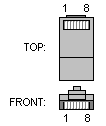
RJ45 interface appearance drawing. Actually, only 4 wires are used for data transmission in 100‑Mbps network, and the other 4 wires are reserved for backup. It transmits digital signals, and the maximum transmission distance of twisted‑pair cable is 100 meters.
10/100BASE‑TX RJ45 Pin Definition
Pin | Name | Description |
1 | TX+ | Transmit Data+ |
2 | TX‑ | Transmit Data‑ |
3 | RX+ | Receive Data+ |
4 | n/c | Not connected |
5 | n/c | Not connected |
6 | RX‑ | Receive Data‑ |
7 | n/c | Not connected |
8 | n/c | Not connected |
The commonly‑used network cable is a straight‑through cable, which means one‑to‑one correspondence. For example, one end follows the T568B wiring standard:
1. White‑Orange
2. Orange
3. White‑Green
4. Blue
5. White‑Blue
6. Green
7. White‑Brown
8. Brown
The other end also adopts T568B standard. Such cables terminated with crystal plugs are used for connection with HUBs, routers and other devices. If you want to connect two PCs directly with a network cable, a crossover cable is required.
Keep one end following the above‑mentioned T568B standard unchanged.
On the other end, swap wire 1 with wire 3, and wire 2 with wire 6 among the 8 conductors. The wire sequence becomes:
1. White‑Green
2. Green
3. White‑Orange
4. Blue
5. White‑Blue
6. Orange
7. White‑Brown
8. Brown
This is the T568A standard for 100‑Mbps network cables, also known as crossover cable.
A cable with one end T568A and the other end T568B, properly crimped, works for direct PC‑to‑PC connection. Summary:
[b]T568A Standard[/b]: White‑Green, Green, White‑Orange, Blue, White‑Blue, Orange, White‑Brown, Brown
[b]T568B Standard[/b]: White‑Orange, Orange, White‑Green, Blue, White‑Blue, Green, White‑Brown, Brown
PC‑to‑PC interconnection requires crossover cable: one end T568A, the other end T568B.
When terminating crystal plugs, orient the plastic latch outward and the cable‑entry opening downward. Arrange wires from left to right according to above sequence. Push conductors fully inside until copper cores are visible at the top of the crystal plug, then crimp firmly with a crimping plier.
Related introduction:
RJ45 plug is a plastic connector that can only be inserted in one direction and locks automatically to prevent disconnection, commonly known as "crystal plug". Its technical name is RJ‑45 connector (RJ‑45 is a network interface specification. RJ‑11, the telephone interface for telephone lines, is a similar specification). It gets the name "crystal plug" for its transparent appearance. Both ends of twisted‑pair cable shall be fitted with RJ45 plugs for plugging into RJ45 jacks of network interface cards (NIC), HUBs or switches for network communication.
Local Area Network (LAN) interconnects independent computers or terminals via network hardware. It exchanges information and realizes resource sharing under specified protocols. Common network cables include twisted‑pair, coaxial cable and optical fiber. Twisted‑pair cables fall into STP (Shielded Twisted‑Pair) with metal shielding and UTP (Unshielded Twisted‑Pair) without shielding. Considering cost‑performance and maintainability, most LANs adopt UTP as transmission medium.
A UTP cable consists of twisted‑pair conductors and RJ45 crystal plugs.
Eight differently‑colored wires are grouped into four twisted pairs. Twisting reduces electromagnetic radiation and external electromagnetic interference. Under EIA/TIA‑568 specifications, twisted‑pair cables are classified by electrical performance into Category‑3, Category‑4 and Category‑5. Cat‑3 and Cat‑5 are most widely used, and Cat‑6 and higher grades are available currently.
Finished network cables connect RJ45 plugs into RJ45 jacks on NIC, HUB or other network equipment. Correspondingly, RJ45 connectors are also rated for Cat‑3 or Cat‑5 performance. An RJ45 crystal plug consists of metal contacts and plastic housing. It has 8 positions (abbreviated as "8P") at the front end, with 8 metal contacts inside the grooves (abbreviated as "8C"), hence the industry term "8P8C". Pay special attention to pin numbering: when metal contacts face you, pins are numbered 1‑8 from left to right. Correct pin sequence is critical for network wiring.
EIA/TIA defines two wiring standards for twisted‑pair cables: T568A and T568B.
T568A Standard:
White‑Green —‑ 1, Green —‑ 2, White‑Orange —‑ 3, Blue —‑ 4, White‑Blue —‑ 5, Orange —‑ 6, White‑Brown —‑ 7, Brown —‑ 8
T568B Standard:
White‑Orange —‑ 1, Orange —‑ 2, White‑Green —‑ 3, Blue —‑ 4, White‑Blue —‑ 5, Green —‑ 6, White‑Brown —‑ 7, Brown —‑ 8
("White‑Orange" refers to light‑orange wire or white wire printed with orange marks; the same rule applies to White‑Green, White‑Brown and White‑Blue).
Arrange twisted‑pair wires to match pin sequence of RJ45 plug one‑to‑one.
For best compatibility, T568B is widely adopted for cable termination. Only one single wiring standard shall be used throughout the whole cabling project. Mixed standards will cause confusion for multi‑person installation. Worse still, cable faults are hard to locate inside bundled cables. Unified T568B is strongly recommended.
In fact, 10Mbps Ethernet only uses pins 1, 2, 3 and 6 for data transmission: pins 1‑2 for transmission, pins 3‑6 for reception. By color: White‑Orange & Orange for transmit; White‑Green & Green for receive. Pins 4‑5 and 7‑8 are bidirectional spare pairs.
100Mbps and 1000Mbps network adapters utilize all four pairs (all 8 conductors). Since 10‑Mbps NIC works fine with cables made for 100‑Mbps application, people usually terminate cables following 100‑Mbps requirements for both 10M and 100M scenarios.
According to connected device types, network cables are divided into straight‑through cables and crossover cables. Straight‑through cables follow identical T568A or T568B standard at both ends. For crossover cables, swap pin1↔pin3 and pin2↔pin6 on one end while keeping the other end unchanged.
Wire sequence of crossover cable:
One end (unchanged) Other end (swapped pairs)
White‑Orange 1 3 White‑Green
Orange 2 6 Green
White‑Green 3 1 White‑Orange
Blue 4 4 Blue
White‑Blue 5 5 White‑Blue
Green 6 2 Orange
White‑Brown 7 7 White‑Brown
Brown 8 8 Brown
Straight‑through cables are used for:
1. Host PC to Switch / HUB;
2. Router to Switch / HUB
Crossover cables are used for:
1. Switch to Switch;
2. Host PC to Host PC;
3. HUB to HUB;
4. HUB to Switch;
5. Host PC direct‑connect to Router
In practical application, the rules can be summarized as follows:
1. Use crossover cables for interconnection between devices of the same type; use straight‑through cables for devices of different types;
2. Routers and PCs belong to DTE (Data Terminal Equipment); Switches and HUBs belong to DCE (Data Communications Equipment);
3. Two termination standards are available for RJ45 connectors: T568A and T568B. Same standard on both ends creates straight‑through cable; different standards create crossover cable.
No matter which wiring scheme you adopt, all 8 indicator lamps shall flash sequentially when tested with an RJ45 cable tester after completion.